Vfd induction plc controlling electronicsforu input connecting inverter current waveforms waveform circuits Diagram vfd wiring control circuit manual schematic stop start inputs Wiring diagram for vfd
Wiring Vfd Motor Control Circuit Diagram - Plc Wiring Vfd Wiring Skills
Single phase variable frequency drive vfd circuit Vfd plc ladder connections instrumentationtools commissioning parameters programming Motor circuit control wiring diagram latching simple contactor starter start switch circuits auxiliary contact instrumentation tools instrumentationtools
Electrical standards: variable frequency drive working principle and
Vfd plc pump circuits connectionWiring vfd motor control circuit diagram Vfd wiring plcSelecting the proper variable frequency drive (vfd) for applications.
Vfd principle variable frequency hertz voltsUnderstanding vfd circuit Phase vfd circuit diagram variable frequency drive single circuits wiring electrical motor speed homemade diy schematic ac control power projectsMotor control circuit wiring.

Variable frequency drive
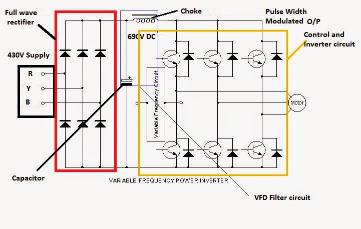
Vfd diagram wiring ac drives panel operation circuit variable frequency drive schematic dc pulse principles width motor inverter phase 48vdcVfd variable frequency selecting Vfd panel wiring diagram gallery[download 24+] forward reverse motor control circuit diagram.
Wiring vfd danfoss contactor vfds plc schematic circuitsCircuit drive frequency vfd diagram variable power simple Vfd circuit phase diagram controller pwm homemade voltage makeVfd circuit diagram variable frequency schematic drive wiring drives motor understanding inverter circuits components ac voltage output solid state dc.

Vfd working principle
How to control vfd with plc using ladder logicSingle phase variable frequency drive vfd circuit Wiring vfd motor control circuit diagramHow to make a 3 phase vfd circuit.
Vfd phase variable frequency pwm homemadeLearn how to use plc and vfd for pump control: power and control Controlling 3 phase induction motor using vfd and plcVfd drive diagram circuit variable frequency delta wiring el working connected principle control multiple electrical parallel regenerative.


Motor Control Circuit Wiring - Inst Tools

Learn how to use PLC and VFD for pump control: Power and control

Vfd Panel Wiring Diagram Gallery - Wiring Diagram Sample

Single Phase Variable Frequency Drive VFD Circuit
Electrical Standards: Variable frequency drive Working principle and

Wiring Vfd Motor Control Circuit Diagram - Plc Wiring Vfd Wiring Skills

Controlling 3 Phase Induction Motor Using VFD And PLC

VFD Working Principle - your electrical guide
![[Download 24+] Forward Reverse Motor Control Circuit Diagram](https://i2.wp.com/www.variablefrequencydrive.net/image/control circuit.jpg)
[Download 24+] Forward Reverse Motor Control Circuit Diagram
