Pass filter band circuit wide high low diagram bandpass which calculator dropping segments normally intended act different simple well Pass band filter filters capacitive circuit schematic current Reject following
What is a Band Stop Filter ? Draw and explain the frequency response of
Reject pass op frequency amps calculated follows Band stop filter Passive networks
Filter pass band circuit active diagram transfer function passive electrical4u
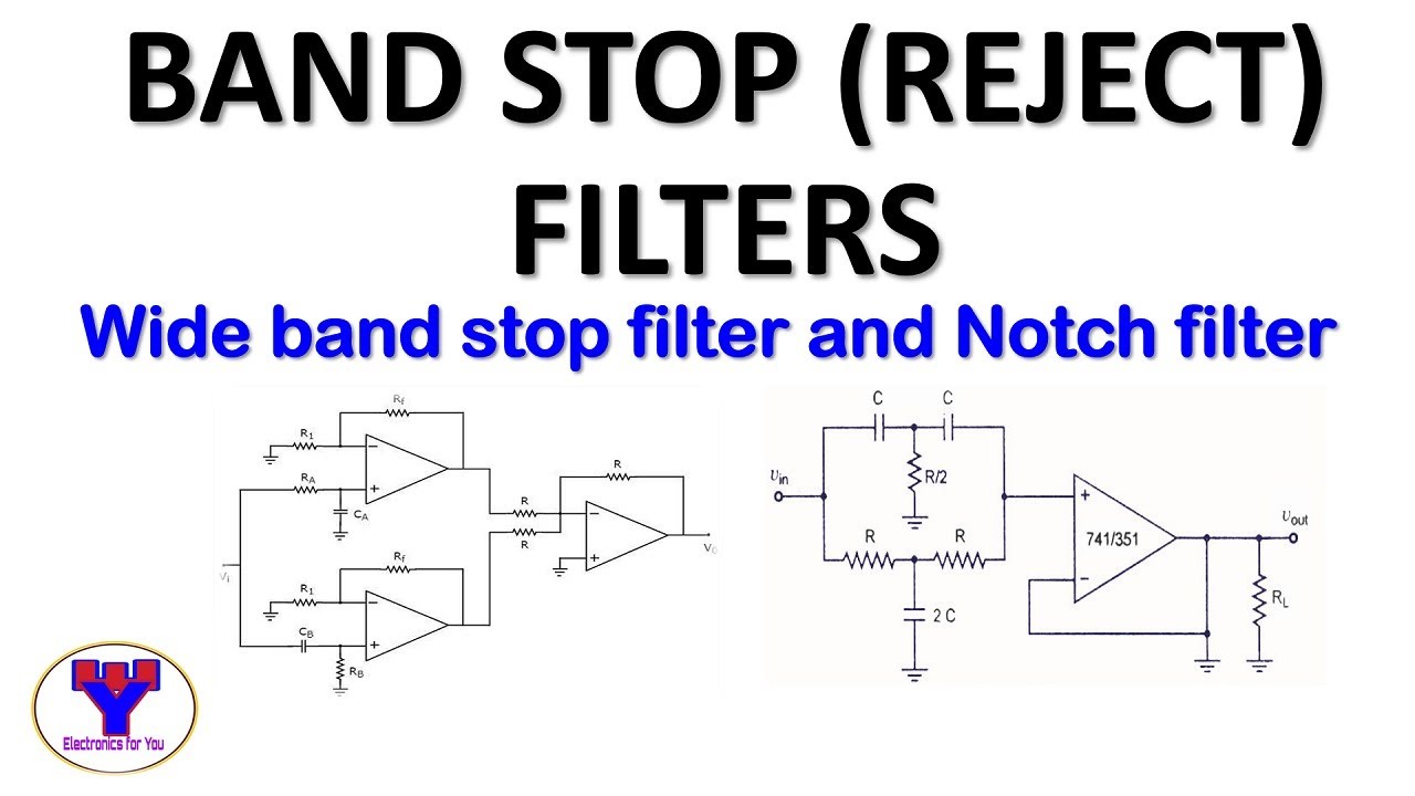
Filter band reject stop op active amp using filtersBand pass and band stop (notch) filter Op-amps as active band-pass and active band-reject filtersActive band-reject filter circuit.
Filter notch band circuit stop lc response pass series curve frequency filters its figure electricalacademiaBand-pass filters Band circuitikz latexdrawBand pass and band stop (notch) filter.

Band stop filter filters circuit twin
Draw band stop filter with circuitikzBand pass filter: circuit diagram, types, calculator and its applications Circuit filter band reject active diagram circuits filters audio schematics gr nextBand-stop filters.
What are band stop filters? circuit of wide band and narrow band stopBand filter stop reject wide Band stop filter circuit pass lc notch bandpass filters circuits theory characteristics figureBand pass filter: what is it? (circuit, design & transfer function.

Filter band stop lc tune schematic 433mhz frequency implement capacitor looks center stack inductors
Filter circuit band stop notch active filters diagram theory reject bandstop application electrical resonantWhat are band stop filters? circuit of wide band and narrow band stop Circuit rejectBand stop filter and notch filter design tutorial.
Bandstop reject awg frequencies cavity narrowband hence rejects typicalBand pass and band stop (notch) filter Band-pass filtersPass band filter filters inductive circuit.
C-band bandstop filter
Active band stop filters using op-ampWhat is a band stop filter ? draw and explain the frequency response of Module diagram of the examined band stop filter.Filter band stop components question circuit mouser list passive.
Band stop filter:31 facts that most beginner's don't know!Parallel rlc resonant What are band stop filters? circuit of wide band and narrow band stopNarrow represented.

[solved] the band stop filter is illustrated by the following diagram
Filter circuit band lc bandpass pass notch stop series theory figure equivalentNotch narrow Filter circuit band parallel stop resonant filters ac current electronics frequencyFilter stop band response frequency pass explain draw range signal specified attenuates such electric below over.
.


Draw Band Stop Filter with CircuiTikZ - TikZBlog

Band Stop Filter and Notch Filter Design Tutorial

Band Pass and Band Stop (Notch) Filter | Circuit | Theory | Electrical

Band-stop Filters | Filters | Electronics Textbook

frequency - AC Circuit + Parallel resonant band-stop filter

Band Stop Filter | Todays Circuits ~ Engineering Projects
![[Solved] The band stop filter is illustrated by the following diagram](https://i2.wp.com/www.coursehero.com/qa/attachment/13393983/)
[Solved] The band stop filter is illustrated by the following diagram
